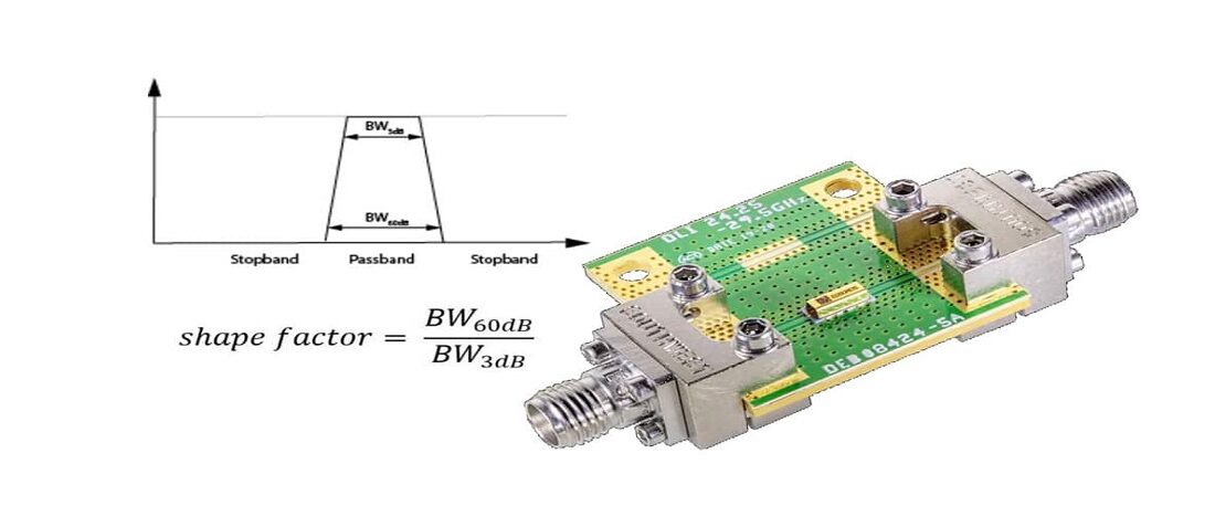
Filter Shape Factor and Selectivity
The Ideal Filter would have a unit gain (0dB) in its passband and a gain of zero (-infinity dB) in its stop band. Between the pass band and stop band, there would be no indecision and would transition from 0dB to -infinity dB asymptotically.
Solved Antenna AGC - V f fif rf RF Amplifier X IF Amplifier

Knowles Precision Devices on LinkedIn: Know Today's RF Filtering Trends to Better Meet the Needs of Tomorrow's RF…
COTS components Archives - EEE Parts Database

404 Not Found

Filter Design Part 2. Explain the Centre Frequency, Cutoff Freq

Band-pass filter - Wikipedia
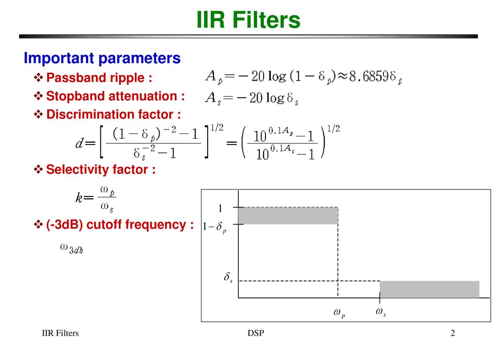
IIR Filters FIR vs. IIR IIR filter design procedure - ppt download

Design of Compact Coaxial Cavity Bandpass Filter with High Selectivity

404 Not Found
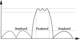
Filter Shape Factor and Selectivity
Filter Basics Part 7 Different Approaches To Q Factor

Bandpass Filter - an overview