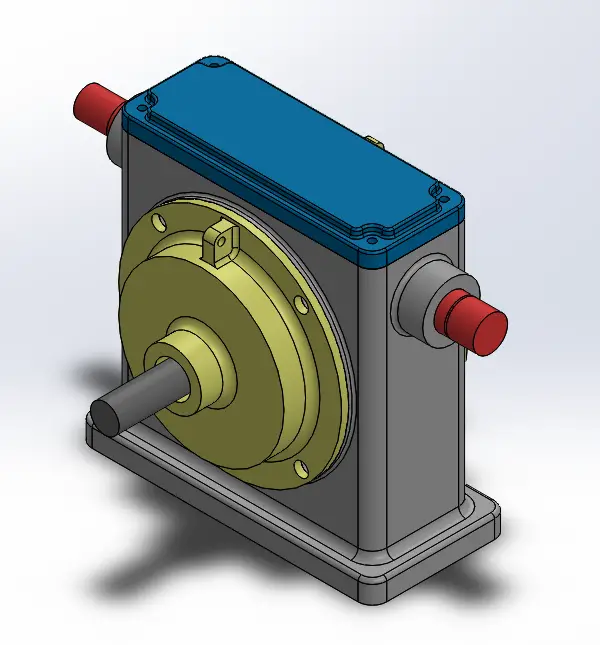
The exploded diagram of the worm gear box assembly. The parts are as
Download scientific diagram | The exploded diagram of the worm gear box assembly. The parts are as follows: 1-cover; 2-bearing; 3-worm shaft; 4-cover; 5-bearing; 6-gear box body; 7-bearing; 8-oil seal; 9-cover; 10-plug; 11-worm gear rim; 12-worm gear hub; 13-output shaft; 14-bearing; 15-oil seal; 16-cover from publication: Image-assisted collision detection for calculation of an assembly interference matrix | The assembly interference matrix is a foundational information model for assembly process planning such as assembly sequence and assembly path planning, and supports digital assembly simulation, intelligent assembly, digital twin-based assembly, and so on. The assembly | Collision Detection, Assembly and Matrix | ResearchGate, the professional network for scientists.
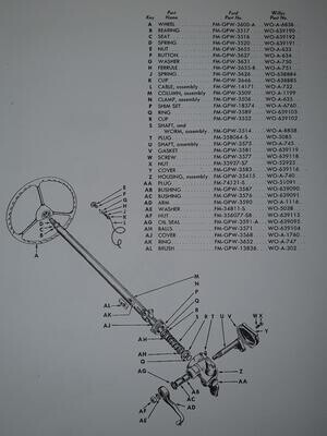
Steering Gear Assembly and Related Parts

slewing ring bearing drive Tracking system, Driving, Engineering tools
Exploded View in SolidWorks: Tutorial - 12CAD.com

Gearbox and Engine Mounts Assembly Parts for Epoxy Series Trowels by Multiquip Whiteman
Gearbox Components and Parts: Everything You Need to Know - Industrial Manufacturing Blog
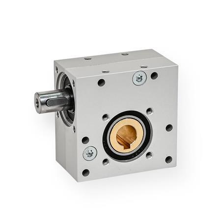
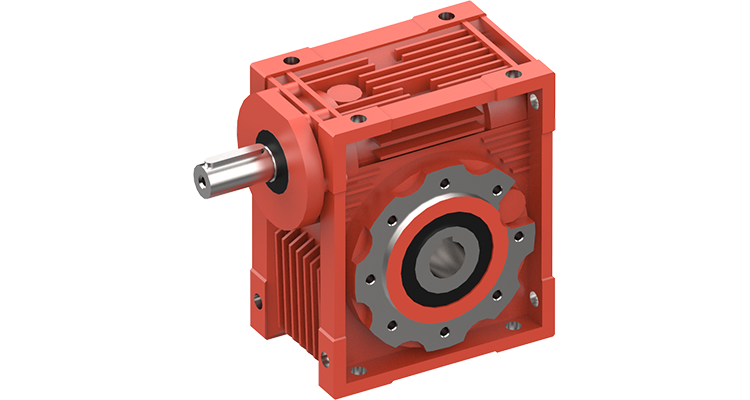
GN 3975 Worm Gear Reducers, Aluminum

Assembly exercise: spur and worm gear (MT 123) – Material Testing Laboratory Equipment

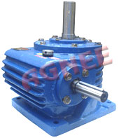
Gearbox - an overview

Image-assisted collision detection for calculation of an assembly interference matrix
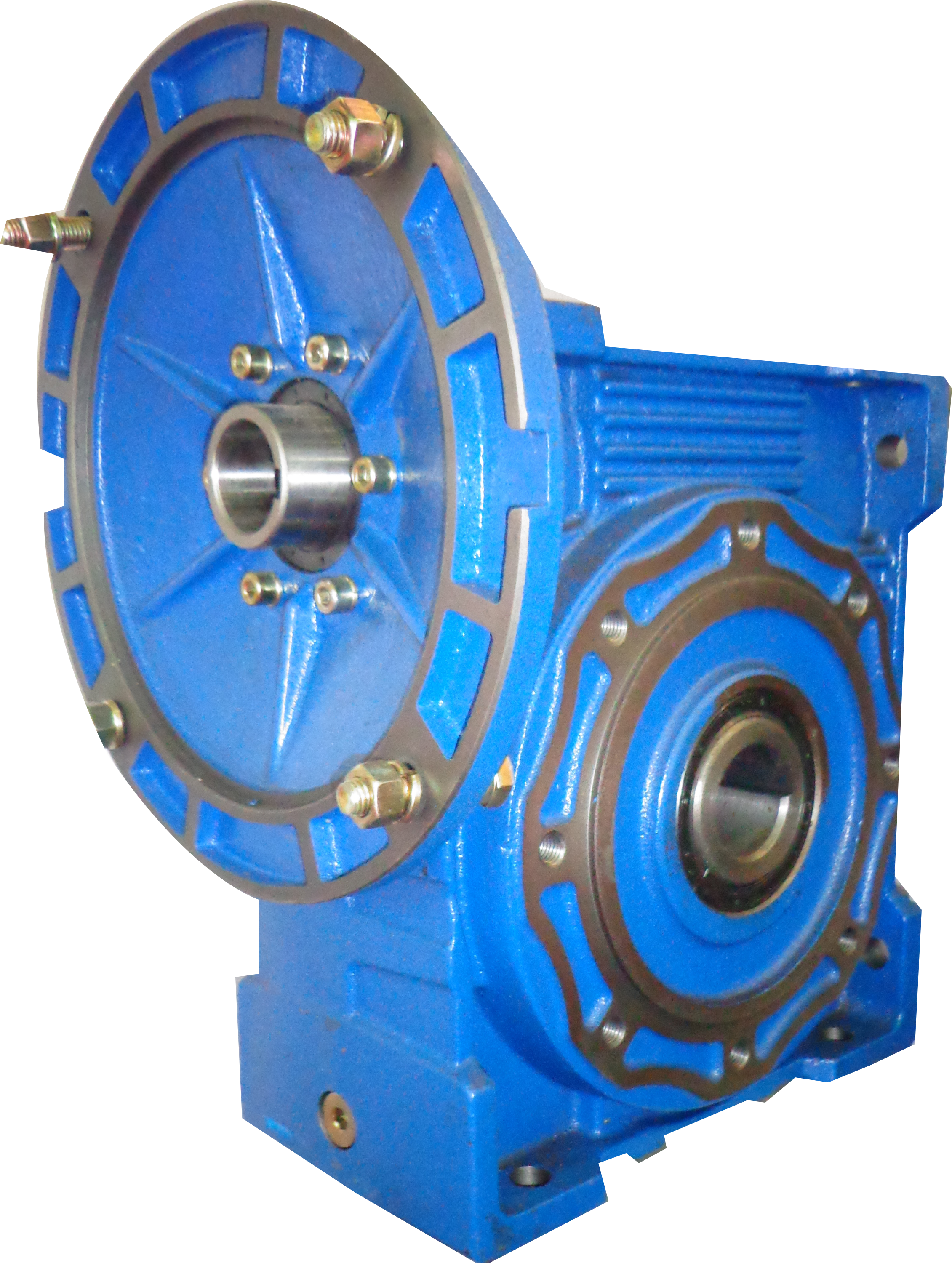
gearboxes